Difference between revisions of "LS-671~VRC"
Jump to navigation
Jump to search
RadioNerds (talk | contribs) |
|||
| Line 45: | Line 45: | ||
;D - Switched 24V out | ;D - Switched 24V out | ||
: 24volts is applied here when PIN C is hooked up, when the power switch is turned on | : 24volts is applied here when PIN C is hooked up, when the power switch is turned on | ||
| + | |||
| + | ;J - Remote PTT | ||
| + | : When the PTT key on the Microphone connected to J1 is pressed, this pin connects to Ground PIN A. | ||
;K - RX Audio in (hook audio to this) | ;K - RX Audio in (hook audio to this) | ||
: receive audio source is hooked here, this shoudl be isolated with a transformer if a 12volt radio is used | : receive audio source is hooked here, this shoudl be isolated with a transformer if a 12volt radio is used | ||
| − | |||
| − | |||
| − | |||
;S - Routed to PIN A, Ground in normal cabling | ;S - Routed to PIN A, Ground in normal cabling | ||
| Line 56: | Line 56: | ||
;U - Transmit Audio | ;U - Transmit Audio | ||
| − | |||
=Hooking up as a simple speaker= | =Hooking up as a simple speaker= | ||
Revision as of 21:45, 8 November 2011
Contents
Overview
This is a simple speaker that is used with the SINCGARS series radios. This speaker can be adapted for use with other systems. This is an amplified speaker and will need 24 volts to function properly.
Usage
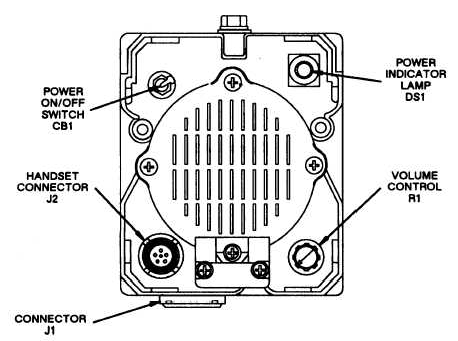
- (CB1) Power ON/OFF Switch
- On Off switch for the powered speaker and accessories connected via pin D
- (J1) Cable Connector
- interface cable connection
- (J2) Handset Connector
- H250 Style handset Microphone connects here
- (DS1) Power Indicator Lamp
- Lamp indicates power is on in the speaker. This can be dimmed by turning the outer housing. The housing can also unscreww to replace the lamp. Uses the common bulb seen on VIC1-Vic4 and many Radios VRC Series and later
- (R1) Volume Control
- This controls the volume for both the Handset connected to J2 and the speaker itself.
- Pushing the knob in, shuts off the external speaker and also provides volume control to the handset mic.
- Pulling out the knob, enables the external speaker and controls its volume.
Pinouts
- A - Ground (Both Audio and Power)
- This is used for both the audio ground and a power ground
- B - Unswitched 24v
- This is used as a constant 24v source into the speaker, to use the speaker this is required as a minumum
- C - Switched 24V in
- This allows 24v to be supplied to PIN D when the power switch is turned on
- D - Switched 24V out
- 24volts is applied here when PIN C is hooked up, when the power switch is turned on
- J - Remote PTT
- When the PTT key on the Microphone connected to J1 is pressed, this pin connects to Ground PIN A.
- K - RX Audio in (hook audio to this)
- receive audio source is hooked here, this shoudl be isolated with a transformer if a 12volt radio is used
- S - Routed to PIN A, Ground in normal cabling
- this is usually the PTT line in VIC1 configurations, since this is routed the Ground, hooking this to a VIC1 using the wrong cable will cause the speaker to key the radio.
- U - Transmit Audio
Hooking up as a simple speaker
Properly interfacing this speaker into 12volt radio, will require the use of an isolation circuit to prevent the 24volt system from harming the 12volt radios. example interfaces can be seen in integrating with other equipment
Below is a simple diagram to hook up receive audio only to server as an external speaker. Note the use of the transformer to isolate the 24volt speaker from the 12volt audio source.
Hooking up for full remote, keying, transmit and receive for non-military radios
coming soon (im still hacking)... feel like adding this? just register and go for it..


