AN/PRC-77
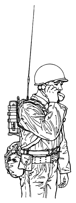
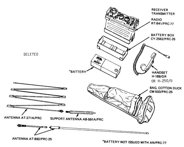
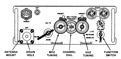
Radio Set AN/PRC-77 is a man-pack, portable, frequency-modulated (fm) receiver-transmitter used to provide short-range, two-way, radio-telephone voice communication. Receiver-Transmitter, Radio RT-841/PRC-77 is also used as part of Radio Sets, AN/VRC-64 and AN/GRC-160 (TM 11-5820-498-12).
Contents
Technical Characteristics
- Frequency range
- Low band
- 30.00 to 52.95 MHz ±3.5 kHz.
- High band
- 53.00 to 75.95 MHz ±3.5 kHz.
- Number of channels
- 920
- Channel spacing
- 50 kHz
- Types of transmission and reception
- Transmission
- Voice (300 to 3,500 Hz) and 150 Hz squelch tone
- Reception
- Voice (no squelch) or voice and 150 Hz squelch tone
- Security or digital data equipment
- Wide band (10 to 20,000 Hz) without 150 Hz squelch tone
- Transmission and reception
- power requirements:
- Transmission
- 12.5 to 15 vdc,780 ma average
- Reception
- 12.5 to 115vdc, 60MA average
- Transmission
- Type of modulation
- Frequency.
- Transmitter output power
- 1.0 to 4.0 W
- Type of squelch
- Tone operated by 150 Hz signal
- Distance range
- 5 mi (8 km) (varies with conditions)
Images
Troubleshooting
It Works, but[1]
If you are checking out a PRC-25 or PRC-77, and you have determined it basically works, but the frequencies are not close, follow this section titled “It works, but...”.
Keep in mind the frequency spec of these wide band radios is +/- 3 khz. So if your radio is within 3 khz of where it is supposed to be, you are done unless you are a perfectionist.
The PRC-25/77 synthesizer is a hybrid system using a phase-locked VCO to derive the mhz portion of the signal, and it mixes it with various crystals to derive the 100 khz and 50 khz steps. So you have several things to check out with a frequency counter or a service monitor:
- The 1 mhz oscillator coming from module A15 – should be fairly close as it is a low-frequency crystal.
- The VCO output, which is locked on to the harmonics coming from the A15 module, via the first mixer and several filter networks. Should be within 2 khz.
- The 50 khz interval oscillator 5.65, 5.6 and 5.55 (PRC-25only) section of the A10 (A40 PRC-77) interval oscillator module. Should be fairly close as they are low frequency crystals.
- The 100 khz interval oscillator, ten crystal frequencies from 46.85- 47.75 mhz, in 100 khz steps. This should be within 2khz. This is where the problems develop as these higher frequency crystals age.
To accomplish this, first measure the 1mhz coming from module A15, and it should be very close. This is present any time the set is on.
Then set the dials to 30.50, and look for 42.000 mhz at A14 J2. This should be within 2khz. Then change the dials to 52.50 and look for 64.000 mhz at A14 J2, plus or minus 2 khz again. If these are both present and within 2 khz, your A9 VCO module is probably OK.
Now check the 50 khz interval oscillator by moving the counter to A10 (A40 in PRC-77) J3, and check for 5.6 mhz when the dial is on an even freq (like 51.00) and then 5.65 when the dial is on 51.05. Now put the dial on 51.00 and key the set and check for 5.55 mhz (PRC-25 only). These should all be very close and usually are not a problem. Note that on the PRC-25 you will have to provide +2.5VDC to pin C of the module to properly bias the switching diodes. Move the +10VDC from the transmit to the receive side and check both (all four in the PRC-25) crystals, which should be within 500 hz.
Now move the probe to A10 (A40 in the PRC-77) J2, and start checking the ten 100 mhz interval oscillator crystals. Start with the dial on an even frequency (like 51.00) and check for 46.85 mhz. All these need to be within 2 khz, and as the crystals age, they get low in frequency. Rotate the dial through .05 .10 .15 etc and check all ten crystals (46.85, 46.95, 47.05, 47.15, 47.25, 47.35, 47.45, 47.55, 47.65 and 47.75) and write down the frequency error for each.
The transformer tuning (white plastic adjustment) on the A10 module will have a small effect on the frequency, but is mostly to peak the circuits RF output. There is no specific frequency adjustment for the crystals. If you find most are a little off in the same direction, you can try the adjustment to bring them on. Since we almost always use these radios on 51.00 mhz, the 46.85 mhz crystal is the most important to be correct.
If you cannot get these within 2 khz, and they are way off, you can replace the crystal or try to find another interval oscillator. If all this checks out, your set should be fairly close to the correct frequency. If not, you have other issues in the synthesizer circuit. Most likely the A20 sidestep oscillator needs minor tweaking to bring the set exactly on frequency.
Reference Files
- OPERATOR’S AND ORGANIZATIONAL MAINTENANCE MANUAL
- RADIO SET
- AN/PRC-77 (NSN 5820-00-930-3724)
- (Including Receiver-Transmitter, Radio RT-841 /PRC-77) (NSN 5820-00-930-3725)
- 1 January 1987
- HAND RECEIPT MANUAL
- COVERIN6 END lTEM/COMPONENTS OF END ITEM (COEI), BASIC ISSUE ITEMS (BII),
- ADDITIONAL AUTHORIZATION LISTS (AAL) FOR
- RADIO SET
- AN/PRC-77 (NSN 5820-00-930-3724)
- December 1978
- ORGANIZATIONAL MAINTENANCE REPAIR PARTS AND SPECIAL TOOLS LIST
- RADIO SET
- AN/PRC-77 (NSN 5820-00-930-3724)
- 15 August 1989
- DIRECT SUPPORT AND GENERAL SUPPORT MAINTENANCE
- REPAIR P ARTS AND SPECIAL TOOLS LISTS
- (INCLUDING DEPORT MAINTENANCE REPAIR PARTS AND SPECIAL TOOLS)
- Radio Set
- AN/PRC-77 (NSN 5820-00-930-3724)
- 15 August 1989
- TECHNICAL MANUAL
- Plastic Laminated Diagrams for Direct and General Support Maintenance
- RECEIVER-TRANSMITTER, RADIO
- RT-841/PRC-77
- 30 SEPTEMBER 1976
- DIRECT SUPPORT, GENERAL SUPPORT, AND DEPOT MAINTENANCE MANUAL
- RADIO SET
- AN/PRC-77 (NSN 5820-00-930-3724)
- February 1968
- Original Scan
![]() PRC-77 Interconnection Diagram
PRC-77 Interconnection Diagram
![]() PRC-77 Mechanism Exploded Views
PRC-77 Mechanism Exploded Views
![]() EMP Hardening Investigation of the PRC-77 Radio Set
EMP Hardening Investigation of the PRC-77 Radio Set
- J.S. Seregelyi, C. Gardener, J.A. Walsh and R. Apps
- Defence Research Establishment Ottowa
- February 1993
References
- ↑ PRC-25 & PRC-77 Problem Log.pdf Used With ,
- Used with permission from the N3OC Website.


