Difference between revisions of "AN~PRC-77"
RadioNerds (talk | contribs) |
RadioNerds (talk | contribs) |
||
| (3 intermediate revisions by the same user not shown) | |||
| Line 194: | Line 194: | ||
===AT-272A Adapter for the PRC-25 and -77=== | ===AT-272A Adapter for the PRC-25 and -77=== | ||
| − | [[File:prc-25-77_comparison_2.jpg| | + | [[File:prc-25-77_comparison_2.jpg|200px|right]]I acquired a PRC-25 about 20 years ago when a friend of mine was cleaning a mini-warehouse storage unit after a deadbeat tenant did not pay his rent. I bought an H-250 handset and both the short and long whip antennas to go with the radio, all at pretty reasonable prices. |
Recently I acquired a couple of PRC-77’s on ebay. Obviously I needed at least one additional antenna in order to equip all three sets with an antenna. But I found that the antennas now seem to be rather scarce and pricy. | Recently I acquired a couple of PRC-77’s on ebay. Obviously I needed at least one additional antenna in order to equip all three sets with an antenna. But I found that the antennas now seem to be rather scarce and pricy. | ||
| Line 205: | Line 205: | ||
====The 50 Cent Solution==== | ====The 50 Cent Solution==== | ||
| − | [[File:prc-25-77_small_adaptor.jpg| | + | [[File:prc-25-77_small_adaptor.jpg|200px|right]]I found that Aircraft Spruce and Specialty Company sells brass tubing with a 5/16 inch diameter and a 0.65 wall thickness for only $5.60 a foot and ordered some. |
Cut off about an inch of the 5/16 tubing. You will need to “mill” abut a half inch length at one end down to about 0.30 inch diameter or a bit less in order to be able to thread it using a 5/16-24 die. I chucked the tubing in my drill press and as it rotated pressed a file against it in order cut down the diameter; this worked surprisingly well. Then I put the tubing in a vice and threaded the cut down end. | Cut off about an inch of the 5/16 tubing. You will need to “mill” abut a half inch length at one end down to about 0.30 inch diameter or a bit less in order to be able to thread it using a 5/16-24 die. I chucked the tubing in my drill press and as it rotated pressed a file against it in order cut down the diameter; this worked surprisingly well. Then I put the tubing in a vice and threaded the cut down end. | ||
| Line 214: | Line 214: | ||
====The $4.00 Solution ==== | ====The $4.00 Solution ==== | ||
| − | A slightly costlier but more solidly built approach is to use 0.75 inch diameter brass rod to make the adapter. I found I could buy 1 inch long pieces of 0.75 in brass rod on ebay, three for $8.30, including shipping. | + | [[File:prc-25-77_large_adaptor.jpg|200px|right]]A slightly costlier but more solidly built approach is to use 0.75 inch diameter brass rod to make the adapter. I found I could buy 1 inch long pieces of 0.75 in brass rod on ebay, three for $8.30, including shipping. |
Take one of the pieces of brass rod and drill a small hole, about 1/8 inch diameter or so, through it lengthwise. Then you need to enlarge the hole in one end to enable you to tap it for ¼-28 thread, such as with a 7/16 drill bit, about a half inch deep. | Take one of the pieces of brass rod and drill a small hole, about 1/8 inch diameter or so, through it lengthwise. Then you need to enlarge the hole in one end to enable you to tap it for ¼-28 thread, such as with a 7/16 drill bit, about a half inch deep. | ||
| Line 225: | Line 225: | ||
So that’s it! It’s not hard to make one of these adapters and while a drill press is a big help you probably can still accomplish it with no more than a handheld electric drill and a vise. | So that’s it! It’s not hard to make one of these adapters and while a drill press is a big help you probably can still accomplish it with no more than a handheld electric drill and a vise. | ||
| + | |||
| + | |||
| + | [[File:prc-25-77_small_adaptor2.jpg|200px]] | ||
| + | [[File:prc-25-77_large_adaptor2.jpg|200px]] | ||
Good luck! | Good luck! | ||
Latest revision as of 15:22, 31 July 2016
Contents
- 1 Overview
- 2 Technical Characteristics
- 3 Images
- 4 Troubleshooting
- 4.1 It Works, but[1]
- 4.2 PRC-25 Transmits Off Frequency Around 3-4khz, but Interval Oscillator Checks Out OK[1]
- 4.3 PRC-77 No Transmit Power Out (Receive OK, Exciter OK, transmit measured approx. 0dbm out)[1]
- 4.4 PRC-77 Low Transmit Power Out (Receive OK, Exciter OK, transmit measured approx. +20dbm out or 100mw)[1]
- 4.5 PRC-77 Transmitter Breaks Up or Sputters (Receive OK)[1]
- 4.6 PRC-25 Synthesizer Out of Lock, Dead A10 50khz Interval Oscillator[1]
- 4.7 PRC-25 & PRC-77 Interval Oscillator (A10) Module Troubleshooting[1]
- 4.8 PRC-25 & PRC-77 Leaky Squelch[1]
- 4.9 PRC-25 & PRC-77 Receives OK with squelch disabled, but goes dead when put on squelch position.[1]
- 4.10 PRC-25 & PRC-77 Intermittent Audio (handset) Connectors[1]
- 4.11 PRC-25 Transmit stops after a few seconds, whine may be heard on tx[1]
- 4.12 PRC-25 & PRC-77 Transmit and receive both off by exactly 1mhz[1]
- 4.13 PRC-25 Synthesizer continuously hunting, slow to lock, or will not lock[1]
- 4.14 PRC-77 Tone Squelch Falsing (annoying sputtering noise)[1]
- 4.15 PRC-25 & PRC-77 Low white noise (low IF noise) PRC-25 & PRC-77 Poor 150hz squelch tone decode[1]
- 4.16 PRC-77 & PRC-25 Low Signal on Low Band, Long Antenna Only[1]
- 5 Modifications
- 6 Reference Files
- 7 References
Overview
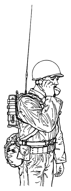
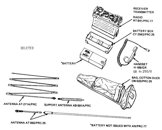
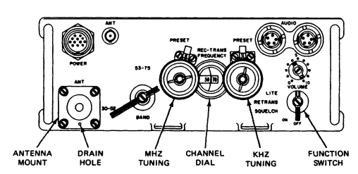
Radio Set AN/PRC-77 is a man-pack, portable, frequency-modulated (fm) receiver-transmitter used to provide short-range, two-way, radio-telephone voice communication. Receiver-Transmitter, Radio RT-841/PRC-77 is also used as part of Radio Sets, AN/VRC-64 and AN/GRC-160 (TM 11-5820-498-12).
Technical Characteristics
- Frequency range
- Low band
- 30.00 to 52.95 MHz ±3.5 kHz.
- High band
- 53.00 to 75.95 MHz ±3.5 kHz.
- Number of channels
- 920
- Channel spacing
- 50 kHz
- Types of transmission and reception
- Transmission
- Voice (300 to 3,500 Hz) and 150 Hz squelch tone
- Reception
- Voice (no squelch) or voice and 150 Hz squelch tone
- Security or digital data equipment
- Wide band (10 to 20,000 Hz) without 150 Hz squelch tone
- Transmission and reception
- power requirements:
- Transmission
- 12.5 to 15 vdc,780 ma average
- Reception
- 12.5 to 115vdc, 60MA average
- Transmission
- Type of modulation
- Frequency.
- Transmitter output power
- 1.0 to 4.0 W
- Type of squelch
- Tone operated by 150 Hz signal
- Distance range
- 5 mi (8 km) (varies with conditions)
Images
Troubleshooting
It Works, but[1]
If you are checking out a PRC-25 or PRC-77, and you have determined it basically works, but the frequencies are not close, follow this section titled “It works, but...”.
Keep in mind the frequency spec of these wide band radios is +/- 3 khz. So if your radio is within 3 khz of where it is supposed to be, you are done unless you are a perfectionist.
The PRC-25/77 synthesizer is a hybrid system using a phase-locked VCO to derive the mhz portion of the signal, and it mixes it with various crystals to derive the 100 khz and 50 khz steps. So you have several things to check out with a frequency counter or a service monitor:
- The 1 mhz oscillator coming from module A15 – should be fairly close as it is a low-frequency crystal.
- The VCO output, which is locked on to the harmonics coming from the A15 module, via the first mixer and several filter networks. Should be within 2 khz.
- The 50 khz interval oscillator 5.65, 5.6 and 5.55 (PRC-25only) section of the A10 (A40 PRC-77) interval oscillator module. Should be fairly close as they are low frequency crystals.
- The 100 khz interval oscillator, ten crystal frequencies from 46.85- 47.75 mhz, in 100 khz steps. This should be within 2khz. This is where the problems develop as these higher frequency crystals age.
To accomplish this, first measure the 1mhz coming from module A15, and it should be very close. This is present any time the set is on.
Then set the dials to 30.50, and look for 42.000 mhz at A14 J2. This should be within 2khz. Then change the dials to 52.50 and look for 64.000 mhz at A14 J2, plus or minus 2 khz again. If these are both present and within 2 khz, your A9 VCO module is probably OK.
Now check the 50 khz interval oscillator by moving the counter to A10 (A40 in PRC-77) J3, and check for 5.6 mhz when the dial is on an even freq (like 51.00) and then 5.65 when the dial is on 51.05. Now put the dial on 51.00 and key the set and check for 5.55 mhz (PRC-25 only). These should all be very close and usually are not a problem. Note that on the PRC-25 you will have to provide +2.5VDC to pin C of the module to properly bias the switching diodes. Move the +10VDC from the transmit to the receive side and check both (all four in the PRC-25) crystals, which should be within 500 hz.
Now move the probe to A10 (A40 in the PRC-77) J2, and start checking the ten 100 mhz interval oscillator crystals. Start with the dial on an even frequency (like 51.00) and check for 46.85 mhz. All these need to be within 2 khz, and as the crystals age, they get low in frequency. Rotate the dial through .05 .10 .15 etc and check all ten crystals (46.85, 46.95, 47.05, 47.15, 47.25, 47.35, 47.45, 47.55, 47.65 and 47.75) and write down the frequency error for each.
The transformer tuning (white plastic adjustment) on the A10 module will have a small effect on the frequency, but is mostly to peak the circuits RF output. There is no specific frequency adjustment for the crystals. If you find most are a little off in the same direction, you can try the adjustment to bring them on. Since we almost always use these radios on 51.00 mhz, the 46.85 mhz crystal is the most important to be correct.
If you cannot get these within 2 khz, and they are way off, you can replace the crystal or try to find another interval oscillator. If all this checks out, your set should be fairly close to the correct frequency. If not, you have other issues in the synthesizer circuit. Most likely the A20 sidestep oscillator needs minor tweaking to bring the set exactly on frequency.
PRC-25 Transmits Off Frequency Around 3-4khz, but Interval Oscillator Checks Out OK[1]
OK your interval oscillator has been checked, but you are still off freq. You can check the 1mhz oscillator but that is such a low frequency it is rarely too far off. Most likely your sidestep oscillator is the culprit. It is a goofy circuit spread over two modules, so any testing of this circuit has to be done with the modules in place in the set, WITH THEIR COVERS ON. When transmitting, look for 11.451mhz at the test point on the top of the A20 module. If it is off frequency, you have found your problem. Fixing it can be a little tricky. This is covered in the third echelon alignment section in the PRC-25 depot manual. Remove the A20 module, and take it’s cover off. Locate T1, the large coil on the left side of the module. It is likely locked in place with glyptol or paint. You will need to hit it with a heat gun to free it up. It is very sensitive, so you only need to move it a little bit. Give it 1/8 of a turn one way or the other, put the cover back on (you can leave the screw out) and pop the module back in the set, key it up, and check again for 11.451mhz at the test point. If it got worse, move it back to the original spot and go 1/8 turn the other way. Once the 11.451mhz is within 500hz, then go back to 51.0 and see if the set is on frequency. It probably will be. You can get them within 1khz and this is the secret to getting old cranky PRC-25’s exactly back on frequency.
PRC-77 No Transmit Power Out (Receive OK, Exciter OK, transmit measured approx. 0dbm out)[1]
About 0dbm transmit power out, with good receive sensitivity and good transmit mod, just low power out. Turned out to be defective antenna relay K1 on A32 module. Replace K1 (difficult) or replace A32 module (available). Relay K1 is a 12vdc DPDT hermetically sealed relay made by Deutsch Relays, with a Deutsch part number of J18C1P6AS-2 and does not seem to be readily available.
PRC-77 Low Transmit Power Out (Receive OK, Exciter OK, transmit measured approx. +20dbm out or 100mw)[1]
This problem turned out to be a bad A37 IPA module. Q2 was defective in the module. Swapping out the module cured the problem. This module is kind of hidden away in the bottom of the radio. You will need to swing up the receive module section of the chassis to get to it. Q2 part number is SM-C-620774 which may sub to NTE-128 or 2N3053.
PRC-77 Transmitter Breaks Up or Sputters (Receive OK)[1]
Unlike the PRC-25, the PRC-77 has separate VCOs for the transmitter and receiver. This problem traced to the A38 module, which is the transmitter VCO module (receive VCO module is the A39, the successor of the PRC-25’s A9 module). Flexing or tapping on the A38 module caused the transmitter to break up. The receive was solid and did not break up. The solution is to replace the A38 module, but they do not seem to be readily available. Opening the module and flexing the boards reproduced the problem. There did not appear to be any bad solder joints or cracked components. However, after flexing some of the components in place, the problem traced to a hard to see bad solder connection on the metal ground bridge that connects the two boards together. It took a lot of time to find this.
PRC-25 Synthesizer Out of Lock, Dead A10 50khz Interval Oscillator[1]
The 5.6mhz portion of the interval oscillator tests fine, but the 46mhz portion of the interval oscillator (A10 module) was totally dead. Turned out to be a cracked 1.8k resistor R3.
PRC-25 & PRC-77 Interval Oscillator (A10) Module Troubleshooting[1]
This module is complicated looking, but very simple to troubleshoot. Verify that the 5.55/5.60/5.65 oscillators are working by connecting a counter or service monitor to J3 test point on the module, and run the radio through transmit and receive with the radio on an even (i.e. 51.00) and an odd (i.e. 51.05) position on the tuning control, and verify all four crystals are working. (The PRC-77 does not have the 5.55mhz crystal.) Then check the 46mhz oscillator by moving the counter or service monitor to J2 test point on the module, and check each crystal by moving the dial through all 100khz positions (i.e. 51.00, 51.10, 51,20, 51,30 etc) and verify all ten crystals are working and on frequency (+/- 2khz). If there is a problem, it is very easy to troubleshoot the module outside the radio. Turn the radio to an even mhz position (i.e. 51.00) and carefully remove the A10 module by either holding back the spring clip that engages the tuning knob shaft while removing the module, or sliding a stiff object like a credit card between the spring clip and the module while removing it. Then get a 9v battery with a 9v battery clip, and connect the red wire to J12-G and the black wire to J12-F to work on the 46mhz oscillator. It is easier to just temporarily solder the red lead to the J12-G pin side of the 1k resistor R18 and solder the black lead to ground than it is to fool with the pins. Then rotate the wafer switch S1B by hand through the positions and troubleshoot each crystal. On the PRC-25, to test the 5.6mhz section, connect the red lead of the battery to J12-E to test the receive 5.60 and 5.65 crystals, and connect the red lead to J12- D to test the transmit 5.55 and 5.60 crystals. Then connect two AA batteries in series (3v) from ground to J12-C. The PRC-77 is a little easier as it does not shift the 5.6mhz section when you transmit, so there are only two crystals to check in this section.
PRC-25 & PRC-77 Leaky Squelch[1]
Both radios use relay K3 to shunt the receiver audio to ground when the radio is squelched. This relay is a 28vdc (oddly enough in a 12v radio but it works) DPDT hermetically sealed relay made by Deutsch Relays. The part number is SM-C-447085 and they are currently available on eBay from userid rf_parts. They do go bad. The symptom is the squelch partially goes quiet, or maybe not at all. The one I observed went partly quiet, but not all the way, with an annoying hiss. Further checking revealed about 8 ohms on the closed relay contact, which should have been 0 ohms. Replacing the relay corrected the problem. The SM-C-447085 relays are occasionally available on eBay. I have seen two PRC-77s with this problem.
PRC-25 & PRC-77 Receives OK with squelch disabled, but goes dead when put on squelch position.[1]
This problem also traces to a bad squelch relay K3. The other set of contacts are involved in the relay function, and if the relay is bad the radio thinks it is in the relay function even though it is not, and stops receiving. Replacing the squelch relay K3 corrected the problem. The SM-C-447085 relays are occasionally available on eBay.
PRC-25 & PRC-77 Intermittent Audio (handset) Connectors[1]
Unfortunately, these can wear out after thousands of handset connections and disconnections. If oxidation is noted on the pins, and the handset is intermittent, use a pencil eraser to clean up the gold contacts on the radio’s connectors. Make sure to blow out all the eraser debris before reconnecting the handset. This fixed a couple I worked on to where they were not quite 100% perfect, but were much better and quite usable.
PRC-25 Transmit stops after a few seconds, whine may be heard on tx[1]
First, check the battery. A dead or marginal battery can stop the DC converter when the voltage gets too low. If you hear the whine for a second or two then it stops, check the battery first. Then check the DC-to-DC converter module A1. They do go bad. The symptom can be full transmit power for a few seconds then suddenly stops, or no transmit at all. The exciter will be heard in a nearby radio, but no watts come out of the antenna jack. Replace the A1 module. They are available from American Milspec. It is also possible to replace the transistors in the A1 module, but since replacement modules are available it is probably not worth the effort.
PRC-25 & PRC-77 Transmit and receive both off by exactly 1mhz[1]
The synthesizer (FSS) is designed to be rich in harmonics, and achieve lock every mhz. Coarse (mhz) adjustment to the VCO is provided by tuning capacitor C1C and C1D, which change when the mhz tuning knob on the front of the radio is rotated. Fine (khz) adjustment is provided by the interval oscillator (A10) module which is connected to the shaft of the khz tuning knob on the front of the radio. Since there are minor variations between C1 from radio to radio, the VCO module (A9 or A38/A39) should be aligned in the radio it is to be used in. If a VCO is not aligned in the radio it is to be used in, the capacitance provided to the VCO by C1C and C1D may be far enough off that it locks to the next mhz above or below the frequency indicated by the radio’s tuning controls. Here are some typical PRC-25 C1C & C1D capacitance readings measured with a capacitance meter from A9J6 pin 5 (C1C) and pin 6 (C1D) to ground with module A9 removed: Mhz RCA C1C 30 24.6pf 31 22.3pf 32 20.1pf 40 9.4pf 50 4.3pf 51 4.0pf 52 3.7pf BRISTOL C1C 21.6pf 19.7pf 17.4pf 9.0pf 4.3pf 4.0pf 3.7pf RCA C1D 38.2pf 36.2pf 33.7pf 19.0pf 8.2pf 7.3pf 6.6pf BRISTOL C1D 35.5pf 33.6pf 31.4pf 17.8pf 7.6pf 6.8pf 6.2pf Note that these values essentially repeat themselves for high band, where 30 would become 53, and 52 would become 75 (add 23). So if your PRC is off frequency by an exact mhz, look in this area for the problem, and make sure your VCO is aligned in the set you are using it in.
PRC-25 Synthesizer continuously hunting, slow to lock, or will not lock[1]
After verifying A9 is properly aligned, and A10 is OK, it turned out to be a cranky A11 module. The module tested OK in another PRC-25, but just was hard to lock in the original radio. When it did lock, the VCO voltage was at the extremes, around 4.8 or 5 volts indicating that it had steered the VCO about as far as it could, which accounted for the difficulty in obtaining a lock. Normal locked VCO voltages are around 3.6 volts, maybe 4 but anything over about 4.5 volts indicates the VCO is struggling to stay locked. After the A9 was correctly aligned in the problem radio, replacing the A11 module locked the VCO perfectly every time. This particular A11 module was the old style and alignment did help some, but it was better to replace it with the improved version of the A11, which is a better circuit than the old version.
PRC-77 Tone Squelch Falsing (annoying sputtering noise)[1]
This was an otherwise perfectly working PRC-77 that unsquelched occasionally, sometimes more often, when no receive signal was present. (Maybe there was a little video being heard, they are pretty wide receivers after all.) The problem turned out someone had misadjusted R5 on the A54 (tone squelch) module where it was too sensitive and unsquelching occasionally just on noise. Turning R5 down a bit solved the problem. I adjusted it where it would reliably unsquelch on a signal with 1.0 khz tone deviation.
PRC-25 & PRC-77 Low white noise (low IF noise) PRC-25 & PRC-77 Poor 150hz squelch tone decode[1]
The symptoms of problems in the A21 (receiver IF) module may be normal or slightly normal receive voice level, but low white noise with the squelch disabled, and possibly poor 150hz tone squelch decode. The IF transformers used in the A21 module are very fragile and prone to damage. This damage can be caused by someone tweaking on them, or can be drop damage causing the head to break off the ferrite transformer slug. The IF module can be aligned by peaking the white noise with no signal, although the manual will tell you to inject a tone and peak with an AC voltmeter. If you have a good ear, just peak the IF transformers for maximum white noise. BE VERY CAREFUL tweaking the IF transformers. They are very fragile!!! Some manufacturers waxed them in place, making them almost impossible to adjust without breaking them. If this is the case, leave them alone! They are probably aligned correctly anyway. Some manufacturers locked them in place with paint, these can probably be aligned. Do not totally remove the slug – there is a cat whisker spring inside that will close up and make almost impossible to put the slug back in. USE A WIDE BLADE screwdriver – the cores are very fragile and if you use a small screwdriver, you will probably damage them. You are after maximum surface area contact here. If you have a broken one as I did, see if you can find a dead A21 module to use for parts, or just swap the whole module. I was able to replace a transformer from a parts mule module, but it was not easy. A21 modules are available now on eBay. Some seem to work, some do not, so buy two if you need one good one.
PRC-77 & PRC-25 Low Signal on Low Band, Long Antenna Only[1]
This problem showed up on a PRC-77 what tested fine on the 50-ohm antenna jack, but in the field it showed severely reduced range on the long (AT-271) antenna. The short antenna worked fine. To test this, you need the low band and high band loads and antenna stud adapter that the book references. I turned down the tip of a 5/16 bolt to match the AB-591 lower screw profile, then cut the top off the bolt at the correct length, and soldered an alligator clip to it. I then prepared a low band, long antenna load of 130 ohms, and a high band, long antenna load of 61.9 ohms in series with a 10pf cap. (To make the 61.9 ohm resistor, start with a resistor of slightly lower value, and file into it slowly until you achieve 62 ohms.) Then the load is attached, and an RF voltmeter is used to measure the RF output at the antenna stud with the microswitches activated, simulating the long antenna. In this case, the RF output was obviously way low on low band, long antenna, just like the symptoms. But the other three possible antenna situations were fine, pegging my RF millivoltmeter. The problem turned out to be the solder tab sticking out of C2A, which tunes the low band, long antenna position along with L4. The solder tab was bent and was touching the outside case of C2, thereby shorting out C2A. (There is normally a DC short on this pin anyway presented by module A32, so there is no way to meter for shorts unless you remove A32 first.) Once the solder tab was straightened out, the low band, long antenna position would peg the RF millivoltmeter just like a good PRC-77 does. A note on the dummy resistor values. The book specifies eight watt resistors, but they are not too common. I used one watt resistors, and they worked OK, just as long as you did not key the radio to long. They do get warm, and that is another way to test for proper output.
Modifications
Carrier Squelch Vs Tone Squelch
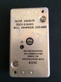
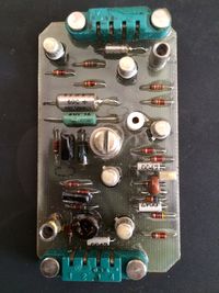
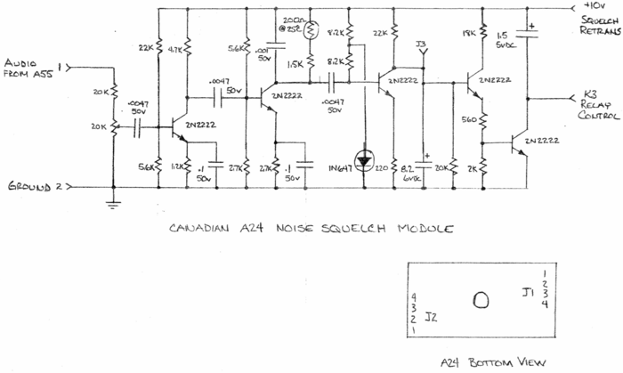
From the factory the US made PRC-77 uses a tone based squelch (150hz), or no squelch at all. This causes issues when attempting to communicate with others using civilian radio gear. You can sometimes have other users of civilian gear set their tone squelch to 151.4 hz, but this may not work. The canadian version of the PRC-77 used a carrier squelch module to overcome this limitation.
AT-272A Adapter for the PRC-25 and -77
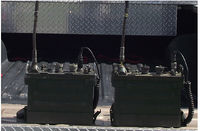
I acquired a PRC-25 about 20 years ago when a friend of mine was cleaning a mini-warehouse storage unit after a deadbeat tenant did not pay his rent. I bought an H-250 handset and both the short and long whip antennas to go with the radio, all at pretty reasonable prices.
Recently I acquired a couple of PRC-77’s on ebay. Obviously I needed at least one additional antenna in order to equip all three sets with an antenna. But I found that the antennas now seem to be rather scarce and pricy.
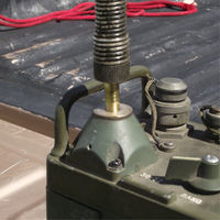
I had acquired an AT-272A whip section, made for a PRC-8-9-10 and I ordered the lower flex base to fit it from Fair Radio Sales for $6.50. The AT-272A base and whip are available from Fair Radio in both new and used condition, but trouble is, the AT-272A will not fit the PRC-25 or PRC-77.
The base of the AT-272A is threaded with a ¼-28 stud. The antenna connection for the PRC-25 and 77 is threaded for a 5/16-24 connection. I decided that it should be possible to make an adapter to enable use of the AT-272A, which is otherwise is almost identical to the later AT-892 whip.
The 50 Cent Solution
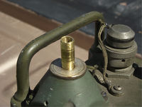
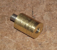
I found that Aircraft Spruce and Specialty Company sells brass tubing with a 5/16 inch diameter and a 0.65 wall thickness for only $5.60 a foot and ordered some.
Cut off about an inch of the 5/16 tubing. You will need to “mill” abut a half inch length at one end down to about 0.30 inch diameter or a bit less in order to be able to thread it using a 5/16-24 die. I chucked the tubing in my drill press and as it rotated pressed a file against it in order cut down the diameter; this worked surprisingly well. Then I put the tubing in a vice and threaded the cut down end.
Then you need to cut internal ¼-28 threads in the other end of the tubing. First you will have to bore out the inner diameter; the recommended size is 0.213 inches, made by a No.3 drill bit. You can use a slightly larger drill bit, like the more common 7/32 size, and that will work adequately.
Take care not to grind the outer diameter down more than about a half inch and also do not drill the inner diameter more than about a half inch to keep from weakening the adapter.
The $4.00 Solution
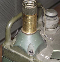
A slightly costlier but more solidly built approach is to use 0.75 inch diameter brass rod to make the adapter. I found I could buy 1 inch long pieces of 0.75 in brass rod on ebay, three for $8.30, including shipping.
Take one of the pieces of brass rod and drill a small hole, about 1/8 inch diameter or so, through it lengthwise. Then you need to enlarge the hole in one end to enable you to tap it for ¼-28 thread, such as with a 7/16 drill bit, about a half inch deep.
The other end of the adapter you need to drill out to enable you to tap it with a 5/16-24 thread. The proper diameter of the hole is 0.2703, but a 9/32 drill bit should work Okay. Don’t drill deeper than about a half inch to prevent
Then take a 5/16-24 bolt and cut the head off, or else buy a 5/16-24 stud, and insert it in the threaded hole. You do not want it sticking out of the brass adapter more than a half inch or else it won’t screw all the way into the radio.
An even simpler to fabricate but slightly more costly version is to get the required special tap and drill bit for a ¼-28 “Helicoil” threaded insert. The drill bit size is also suitable for a hole than can be threaded to 5/16-24 and the other end can be threaded for the ¼-28 Helicoil reinforcement to produce a stronger fitting.
So that’s it! It’s not hard to make one of these adapters and while a drill press is a big help you probably can still accomplish it with no more than a handheld electric drill and a vise.
Good luck!
Wayne
WB5WSV
Reference Files
- OPERATOR’S AND ORGANIZATIONAL MAINTENANCE MANUAL
- RADIO SET
- AN/PRC-77 (NSN 5820-00-930-3724)
- (Including Receiver-Transmitter, Radio RT-841 /PRC-77) (NSN 5820-00-930-3725)
- 1 January 1987
- HAND RECEIPT MANUAL
- COVERIN6 END lTEM/COMPONENTS OF END ITEM (COEI), BASIC ISSUE ITEMS (BII),
- ADDITIONAL AUTHORIZATION LISTS (AAL) FOR
- RADIO SET
- AN/PRC-77 (NSN 5820-00-930-3724)
- December 1978
- ORGANIZATIONAL MAINTENANCE REPAIR PARTS AND SPECIAL TOOLS LIST
- RADIO SET
- AN/PRC-77 (NSN 5820-00-930-3724)
- 15 August 1989
- DIRECT SUPPORT AND GENERAL SUPPORT MAINTENANCE
- REPAIR P ARTS AND SPECIAL TOOLS LISTS
- (INCLUDING DEPORT MAINTENANCE REPAIR PARTS AND SPECIAL TOOLS)
- Radio Set
- AN/PRC-77 (NSN 5820-00-930-3724)
- 15 August 1989
- TECHNICAL MANUAL
- Plastic Laminated Diagrams for Direct and General Support Maintenance
- RECEIVER-TRANSMITTER, RADIO
- RT-841/PRC-77
- 30 SEPTEMBER 1976
- DIRECT SUPPORT, GENERAL SUPPORT, AND DEPOT MAINTENANCE MANUAL
- RADIO SET
- AN/PRC-77 (NSN 5820-00-930-3724)
- February 1968
- Original Scan
![]() PRC-77 Interconnection Diagram
PRC-77 Interconnection Diagram
![]() PRC-77 Mechanism Exploded Views
PRC-77 Mechanism Exploded Views
![]() EMP Hardening Investigation of the PRC-77 Radio Set
EMP Hardening Investigation of the PRC-77 Radio Set
- J.S. Seregelyi, C. Gardener, J.A. Walsh and R. Apps
- Defence Research Establishment Ottowa
- February 1993
