Difference between revisions of "Control, Bomb release Type B-2A"
RadioNerds (talk | contribs) |
RadioNerds (talk | contribs) |
||
| Line 16: | Line 16: | ||
; Sel / Train : not sure what this is for. | ; Sel / Train : not sure what this is for. | ||
| − | To | + | |
| + | |||
| + | ===To Operate=== | ||
#Set the "bombs to be released" to the number of pulses (1-50), | #Set the "bombs to be released" to the number of pulses (1-50), | ||
#Set the time delay | #Set the time delay | ||
| Line 23: | Line 25: | ||
The sequence will stop once the counter reaches zero. you can also make a simple modification to prevent it from stopping, basically pulsing forever until you move the "Sel / Train" switch to "Sel" | The sequence will stop once the counter reaches zero. you can also make a simple modification to prevent it from stopping, basically pulsing forever until you move the "Sel / Train" switch to "Sel" | ||
| + | |||
| + | |||
| + | ===Modifying to Allow Continuous Operation=== | ||
| + | |||
| + | Inside the unit is a set of switch contacts that are separated when the counter turns to zero, by connecting these wires together, they never break connection, allowing the sequence to continue endlessly. | ||
| + | |||
| + | #Open the back cover | ||
| + | #Remove the two tubes | ||
| + | #identify the shut off switch, see picture | ||
| + | #Solder two jumpers one between each point identified in the picture below. | ||
| + | |||
| + | <gallery widths=100px heights=100px perrow=5> | ||
| + | File:Type_b-2a_modify_step3.jpg | ||
| + | File:Type b-2a_modify_step4.jpg | ||
| + | </gallery> | ||
| + | |||
===Schematic=== | ===Schematic=== | ||
Revision as of 20:48, 1 March 2012
The bomb release timer used on many US made WWII aircraft was used to time the release of bomb out of the aircraft. This allowed the pilots to accurately space the impact of the bombs based on airspeed. Generally the timing is adjustable from 0.08 second to 1 second between pulses. The B-2A connects two pins together on every pulse. These pins can be used to complete a circuit to drive a relay or similar switched item.
NOTE: It does not provide any voltage on the connected pins, only acts as a momentary switch.


There are three main controls
- Interval Between Bombs
- Controls the time between the pulses
- Bombs to be released
- controls the number of pulses 1-50
- Sel / Train
- not sure what this is for.
To Operate
- Set the "bombs to be released" to the number of pulses (1-50),
- Set the time delay
- Set the "Sel / Train" switch to "Train"
- connect Pin #1 to Pin #4 momentarily to begin the sequence
The sequence will stop once the counter reaches zero. you can also make a simple modification to prevent it from stopping, basically pulsing forever until you move the "Sel / Train" switch to "Sel"
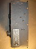
Modifying to Allow Continuous Operation
Inside the unit is a set of switch contacts that are separated when the counter turns to zero, by connecting these wires together, they never break connection, allowing the sequence to continue endlessly.
- Open the back cover
- Remove the two tubes
- identify the shut off switch, see picture
- Solder two jumpers one between each point identified in the picture below.


Schematic

Hookup

Pins
- Pin 1
- Start Cycle
- Pin 2
- Output contact point
- Pin 3
- Not used
- Pin 4
- + 24 Volt
- Pin 5
- - 24 Volt
Videos
[1] Video Of Operation, Front View
[2] Video of Operation, Rear View
Other Images
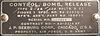
Data Plate
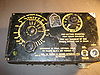
Front
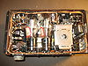
Bottom
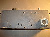
Side
Side


